Carbon capture and storage
Locking carbon underground or on the seabed is a cumbersome, risky and costly storage strategy. The gas does not go away; it only moves.

Ağır Sanayi ve Yapı Tesisleri
Çevre Teknolojileri & Geri Kazanım
Endüstriyel & Yapı Tesisleri
Enerji Santralleri
Kazan Sistemleri (Boilers)
Kırma ve Hazırlama
Kurutma Teknolojileri
Mühendislik & Taahhüt Hizmetleri
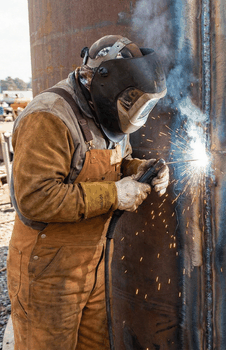
Not capture. Breakdown at the source.
SGPT is neither a filter nor a storage system. It is a thermocatalytic, electromagnetic-resonance unit that breaks CO₂, CO and NOₓ down at source into their elements: solid carbon, oxygen and nitrogen.
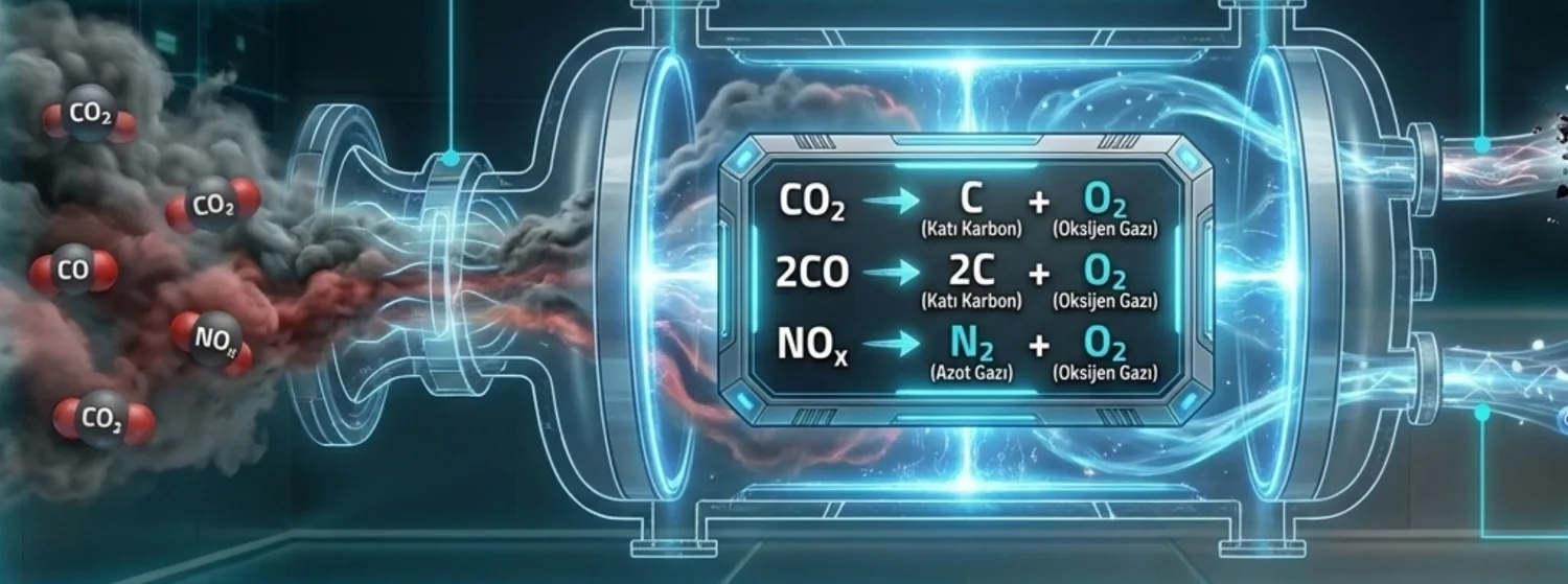
Current approaches either store greenhouse gas underground or on the seabed, or turn one gas into another. The targets of the Kyoto Protocol and the Paris Agreement call for more fundamental steps.
Locking carbon underground or on the seabed is a cumbersome, risky and costly storage strategy. The gas does not go away; it only moves.
It burns toxic CO and produces extra CO₂ in the process. The greenhouse effect is not reduced; pollution just changes form.
Conventional systems depend on high exhaust temperatures and on precious metals such as platinum and rhodium.
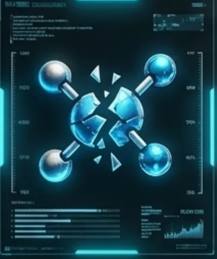
Target gases (CO₂, CO, NOₓ) are not captured; they are broken down into their elements at molecular level.
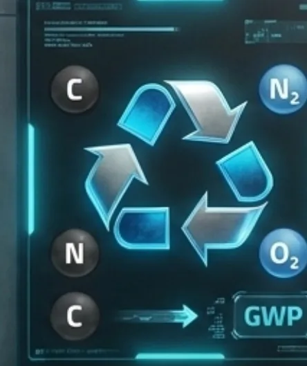
Toxic emissions are converted into industrial-grade solid carbon (C), nitrogen (N₂) and oxygen (O₂). The outputs have a global warming potential (GWP) of zero.

Designed to EPA and EU directives, the SI unit system and ASME/API standards. Capacity scales by adding modules.
CO₂ is one of the most stable molecules, with some of the strongest interatomic bonds. Rather than heating the whole gas mass, SGPT overcomes this barrier by directing energy precisely at the bond itself.
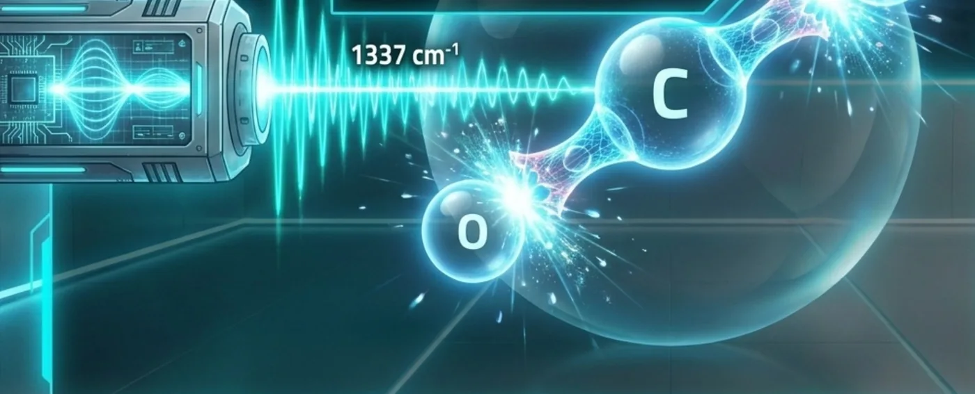
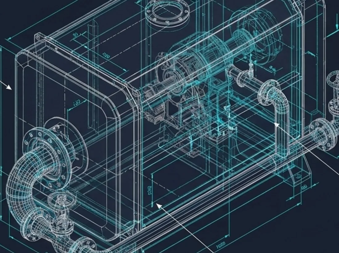
Three core reactions take place in a reactor built to the ASME pressure-vessel standard. All incoming gases become elements with no greenhouse effect.
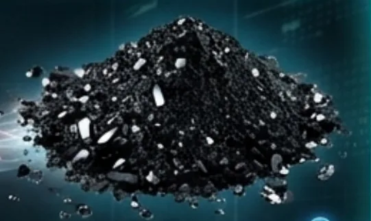 By-product 1: pure solid carbon (C)≈ 484,5 g
Calculation: 40.34 mol × 12.011 g/mol C = 484.5 g; 40.34 mol × 31.998 g/mol O₂ = 1,290.8 g. Stoichiometric values assuming full conversion; the actual conversion rate is measured on site and depends on gas composition and residence time.
Test conditions: silica column, helium carrier, 10 ml/min flow, TCD at 150 °C. Oven profile: controlled ramp from 50 °C to 200 °C to separate light gases. Results are per 1 ml gas injection.
Calculated volume: 602 × 0.0005 = 0.3 ml. After treatment the area approaches zero.
Calculated volume: 1,448 × 0.0005 = 0.7 ml. A measured increase in free oxygen.
Real values measured with a BILSA exhaust emission analyser on a petrol/LPG vehicle installation.
Reduction in CO concentration by volume.
Reduction in CO₂ concentration by volume.
No measurable level left of the gases that cause acid rain.
Free-oxygen formation raised the air/fuel ratio.
Field values come from a single vehicle installation. For industrial sources, performance is measured and reported per project, based on gas flow, composition and temperature.
| Criterion | Conventional catalytic converter | NEO SGPT |
|---|---|---|
| CO₂ handling | Does not reduce CO₂. Burns CO and adds CO₂. | Splits the CO₂ molecule directly. |
| Operating conditions and energy | Needs high exhaust temperature and precious metals such as platinum/rhodium. | Runs on low-power, point-focused electrical energy. |
| Output | Turns one toxic gas into another greenhouse gas. | Harmless elements: C, O₂, N₂ (GWP = 0). |
The carbon collected in the reactor is not waste but a saleable product, turning the unit into a source of income that offsets its running costs.
The roughly 484.5 g of carbon separated from every 1 m³ of CO₂ is discharged automatically by a rotary valve and pneumatic conveyors so the system never clogs.
The collected mass is weighed in real time by load cells and reported to ERP/SCADA as a digital carbon-footprint record.
The pure carbon is sold back to industry as carbon black, paint pigment and rubber filler.
Modular integration into car and commercial-vehicle exhaust lines to cut carbon-emission liabilities.
Cement, brick and iron-and-steel plants. No need for scrubber/FGD wastewater ponds, with a targeted footprint reduction of up to 80%.
At coal- and gas-fired plant stacks: on-site breakdown instead of carbon capture and storage.
Cutting urban air pollution at residential boiler rooms and district-heating stacks.
Talk to our engineers about a preliminary assessment and capacity projection for your emission source.